PID Controllers
The PID (Proportional-Integral-Derivative) controller is a widely used control algorithm in the field of robotics. It is an essential tool for controlling motor speed, position, and many other dynamic systems.
Control Terms
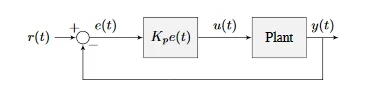
A PID Controller is consisted of three terms that control its output.
| Letter | Term | Description |
|---|---|---|
| P | Proportional | proportional to the current error between the desired setpoint and the measured process variable. |
| I | Integral | accumulates the error over time and provides a long-term correction to the control signal. |
| D | Derivative | proportional to the rate of change of the error signal. It provides a damping effect to the control signal |
Definitions
- Setpoint: The desired value of the process variable.
- Process Variable: The value of the variable being controlled.
- Control Signal: The output of the PID controller.
Nomenclature
The following nomenclature will be used to describe the PID controller's equations in this section.
| Notation | Definition |
|---|---|
| e(t) | Error |
| u(t) | Control signal |
| r(t) | Setpoint |
| y(t) | Process variable |
| Variable | Definition |
|---|---|
| Kp | Proportional gain |
| Ki | Integral gain |
| Kd | Derivative gain |
Proportional Term
The Proportional term is responsible for adjusting the control output proportionally to the current error. This means that the larger the error, the larger the corrective action applied to the system.
Kp Proportional Gain
The Proportional gain, represented by the variable K determines the strength of this correction. A higher value of Kp results in a stronger correction for a given error.
The control signal of the proportional term is calculated as follows:
u(t) = Kpe(t)
The proportional gain is multiplied by the error to produce the control signal.
A simple P controller can be modelled as follows:
A Physics Analogy
In Hooke's Law, the force applied by a spring is proportional to the displacement from its equilibrium position. Similarly, the P value in a PID controller determines the proportional response of the controller to the error signal, which is the difference between the desired setpoint and the actual measured value.
Just as a stiffer spring will apply a larger force for the same amount of displacement, a higher P value will result in a larger correction for the same amount of error. However, if the P value is set too high, just like a spring that is too stiff, the controller's response will become too sensitive and can lead to overshooting or oscillations. Therefore, the P value needs to be carefully tuned to provide the appropriate proportional response to the error signal, resulting in stable and accurate control.
Integral Term
The Integral term is responsible for adjusting the control output based on the accumulated error over time. This means that the longer the error persists, the larger the corrective action applied to the system.
FRC Use
Integral gain is not recommended for FRC use. It is usally better to use a feedforward controller to eliminate steady-state error. It is included here for completeness.
Ki Integral Gain
The Integral gain, represented by the variable Ki determines the strength of this correction. A higher value of Ki results in a stronger correction for a given error.
The control signal of the integral term is calculated as follows:
u(t) = Ki ∫e(t)dt
The integral gain is multiplied by the integral of the error to produce the control signal.
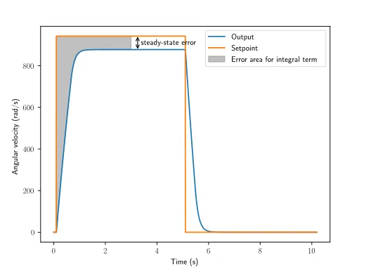
The Steady State Error
Steady State Error
When the system is close the setpoint in steady-state, the proportional term may be too small to pull the output all the way to the setpoint, and the derivative term is zero. This can result in what is called a steady-state error.
Definition
- Steady-state error is the difference between the setpoint and the process variable when the system has reached a steady-state.
Graph
Solution to Steady State
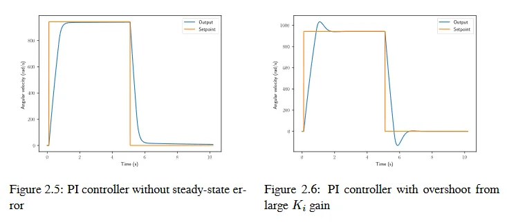
Using the Integral term we can solve this issue. Because the integral term accumulates the error over time, it will continue to increase until the error is zero. This means that the integral term will continue to increase until the steady-state error is eliminated.
Seen in the figure below
Derivative Term
The Derivative term is responsible for adjusting the control output based on the rate of change of the error. This means that the faster the error changes, the larger the corrective action applied to the system.
Kd Derivative Gain
The Derivative gain, represented by the variable Kd determines the strength of this correction. A higher value of Kd results in a stronger correction for a given error.
The control signal of the derivative term is calculated as follows:
u(t) = Kd de(t)/dt
The derivative gain is multiplied by the derivative of the error to produce the control signal.
FRC Use
The derivative term is less used in frc applications.
How it works
The derivative term works by calculating the slope of the error signal over time, which gives an indication of how quickly the error is changing. This information can be used to predict the future behavior of the system and to adjust the control output accordingly.
When the error is changing rapidly, the derivative term produces a large correction signal, which helps to dampen the system's response and prevent overshoot. On the other hand, when the error is changing slowly, the derivative term produces a smaller correction signal, which allows the system to respond more quickly to changes in the setpoint.
Predictive
The derivative term can be thought of as a "predictive" element in the PID controller, since it uses information about the rate of change of the error signal to anticipate future changes in the process variable.
Tuning a PID Controller
There are multiple different ways to tune a PID controller.
For our purposes we use a trial and error method. There are alternatives such as the Ziegler-Nichols method, but they are not covered here.
Time Consuming
This method can be time-consuming and requires a good understanding of the system's behavior.
Manual tuning involves adjusting the proportional, integral, and derivative gains manually by trial and error. This method involves observing the system's response to changes in the setpoint and adjusting the gains to achieve the desired response.
Summary
A PID (proportional-integral-derivative) controller is a control algorithm used in control systems to regulate a process variable, to a desired setpoint. The controller calculates an error signal, which is the difference between the setpoint and the actual value of the process variable. The controller then uses three components: the proportional term, the integral term, and the derivative term, to adjust the control output and bring the process variable closer to the setpoint.
The Terms
- The proportional term provides a control output proportional to the error signal
- The integral term takes into account the past error and accumulates it to reduce the steady-state error
- The derivative term considers the rate of change of the error signal to predict the future behavior of the system.
By using all three components (tuned correctly), a PID controller can respond to changes in the process variable quickly and accurately, and maintain stable control in the face of disturbances and other external factors.
Created: April 25, 2023